Visualizing the Layers of the TCP/IP Model
Part 2 of The Strangest Explanation of VLANs You've Never Heard series, expanding on basic topological concepts by adding dimensions to the TCP/IP stack.


This is part 2 of a series, The Strangest Explanation of VLANs You've Never Heard. While it should be largely capable of standing alone, it does build on some of the topological concepts discussed in that article. This should provide what I find to be a useful shift in perspective for understanding and better utilizing the concepts of the TCP/IP and OSI models. I'd recommend reading through the series in order to get the most out of it, as I've tried my best to present idea in the most linear way I could think of.
 Nad
Nad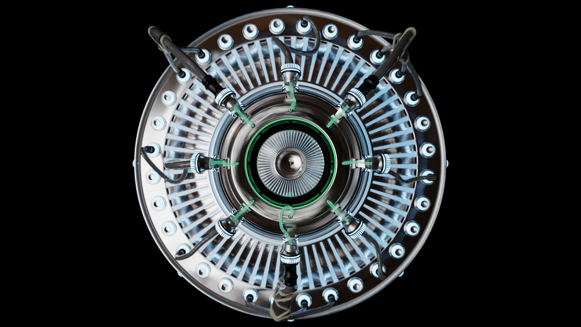
Physical and Logical
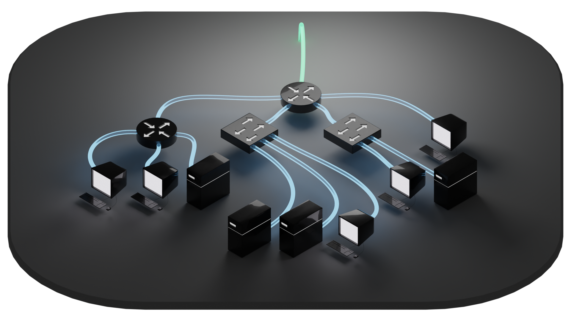
Because networks don't just live in the more abstract world of programming, but also have tendrils that connect out to other physical devices, it's important to examine the concepts that are commonly utilized. Network diagrams, for example, can be designed to convey physical configuration of devices and wiring. Or they can be diagrams designed to convey crucial aspects of logic that define the network topology. It can be confusing to look at a diagram expecting a physical layout when it is in fact a logical diagram.
In a physical network diagram, a gateway router that also serves as a firewall and a wireless access point can be represented by a single node. But on a logical diagram, there might be good reason to want to break out those specific features to their own independent nodes. A device present on a physical diagram might not have any reason to be present on a logical diagram if it has no effect on the topology being described.
Similarly, a router as a physical device can be employed in a use case where it serves the same logical function as a another type of device, such as the above example of a flat network where a router is being employed as a switch. Just because it is a router doesn't mean it has to route. This doesn't have much of an effect on a physical layout, but it can fundamentally alter the logical configuration. This can sometimes be described by referencing which "layer" a given device accesses.
So let's drill down through these so-called layers real quick to find some tools that will help us describe the logical arrangement of networks. For that, we're going to have to take a short dive into the TCP/IP and OSI models.
The TCP/IP model was created as a framework to implement a network protocol and was originally described in RFC 1122 and RFC 1123 (RFCs, Request For Comments, are publications through which many of the standards of the internet are established). The framework describes standards of communication across a network within protocols, and established a model of visualization using layers that is commonly referenced to communicate key features of those protocols.
The OSI model was developed as an updated version designed to break down TCP/IP's layers into more granular components. While the TCP/IP model is implemented in protocols, OSI is more for reference purposes. The numbering system of OSI is most commonly referenced because the extra delineations can be very useful.
Yes, this does indeed lead to confusion. To add to it, the numbering starts at the bottom, but the formation of data starts at the top. Hence my earlier phrasing of "drill down" and "short dive", as the formation of data is the more crucial aspect when it comes to mapping the concepts out.
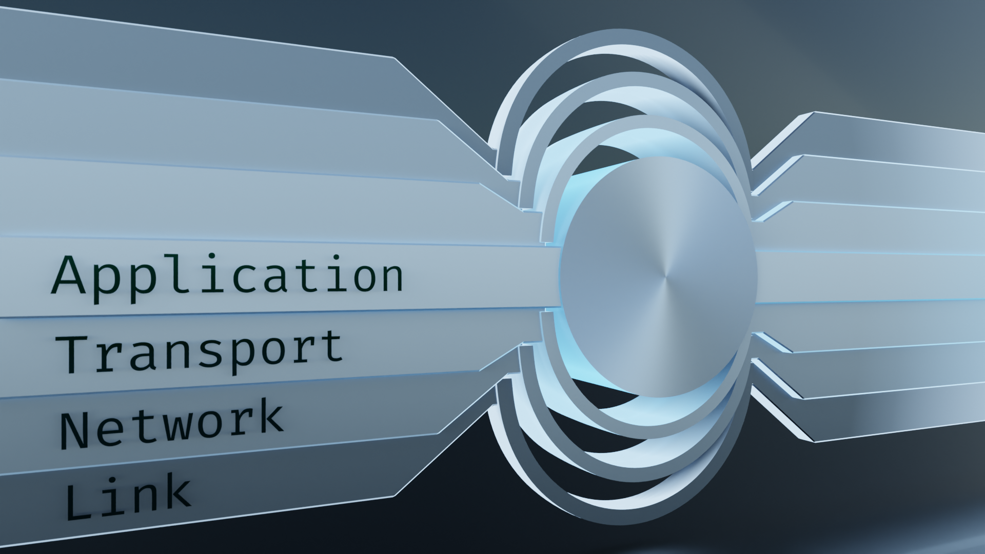
So how do TCP/IP and OSI stack up against each other?
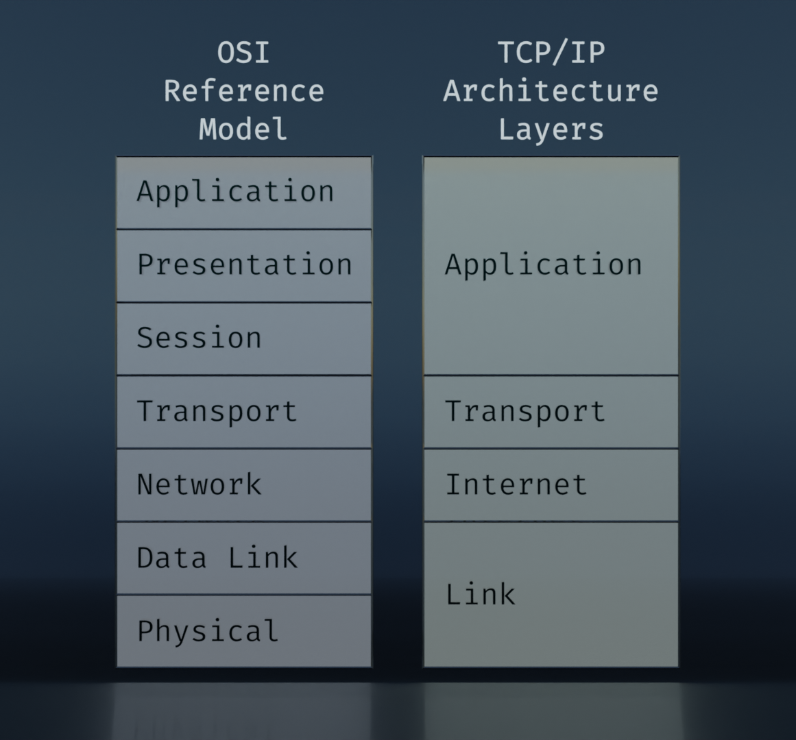
This is the usual form that they are presented in. The idea behind these is that, starting at the top, an application needs to communicate with another device, and it packages the data it needs to send. More data is added to that to facilitate the transfer. The added data is broken up into groupings defined roughly on the spectrum of software to hardware, or logical to physical. We'll get into more detail on this soon.
I'm not a fan of this representation because it doesn't lend itself well to visualizing how various steps along the way access the different layers. But the comparison is useful for noting the additional delineations of the OSI model, and how they correlate to the TCP/IP layers.
There are "updated" versions of the TCP/IP layers that attempt to add in aspects of the OSI model (differentiating between Data Link and Physical in particular), but in my opinion it's like trying to plug a leak in a swimming pool by throwing a blanket over the top of it. The solution does not address the problem and only succeeds in muddying the water.
The problem with this visualization is that it's layering things on top of each other like a sandwich. What we should be doing is visualizing it in terms of encapsulation. Matryoshka dolls come to mind.
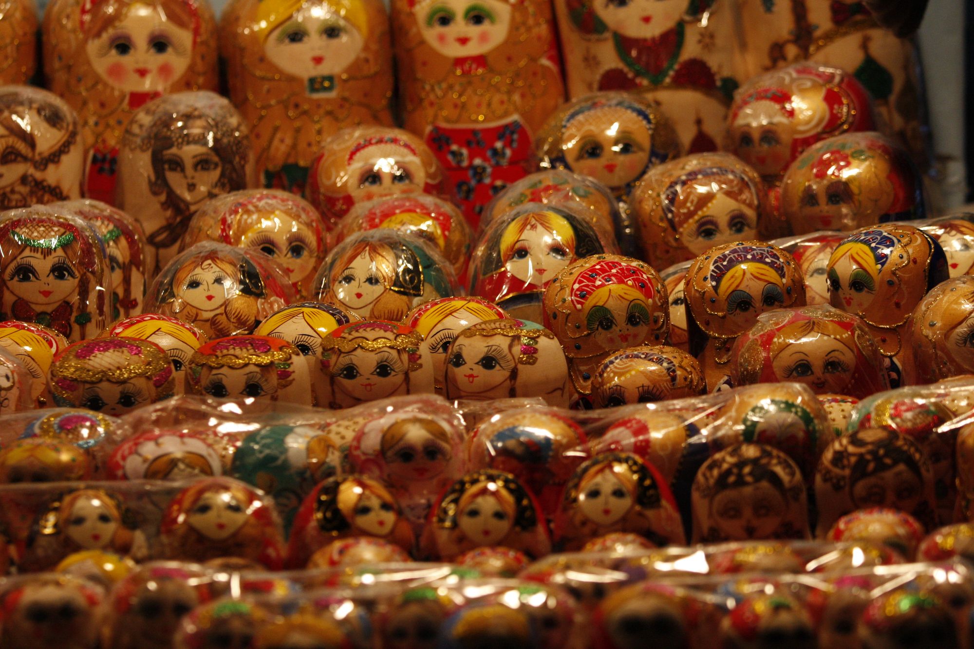
These nifty little doo-dads fit the bill nicely. They are layered. They can be readily disassembled, examined, and reassembled. Each of the layers can stand alone and contains its own unique information. Let's go with this.
The key concept here is encapsulation. When a program is called to communicate with another similar program through a connection, it will first form a payload to send to the remote program. Large chunks need to be broken up into smaller pieces. Those smaller pieces make up the core of a packet. In addition to that core, though, there needs to be additional information to provide to the network that will facilitate its journey. Information like where it's coming from, where it's going, which piece of the whole it is, and possibly some security features that might come in handy. In other words, it needs supplies for the trip. Around the core, these additional layers are encapsulated in a standardized way.
Referring over to the word-shenanigans in the companion VLAN article, encapsulation is akin to envelopment. We're taking a thing and enclosing it within another. And recalling back to our tools of topological tinkering, each subsequent layer of encasement can still maintain its own distinct boundary manifold.
Ultimately, we want that package to travel down along a line, or wifi signal, or whatever other means of transportation is available to it, and find its destination. During the short stops along its passage, it needs to check in with, say, a ticket booth at yonder router. Or it might need to get its port number checked at a firewall. Thankfully, our packet is prepared and organized with all the bits in the right layers. The topological manifolds are consistently correct, otherwise the packet gets "dropped."
In other words, the topology of the packet must be compatible with the topology of the interfaces it passes through. The "shapes" must correspond.
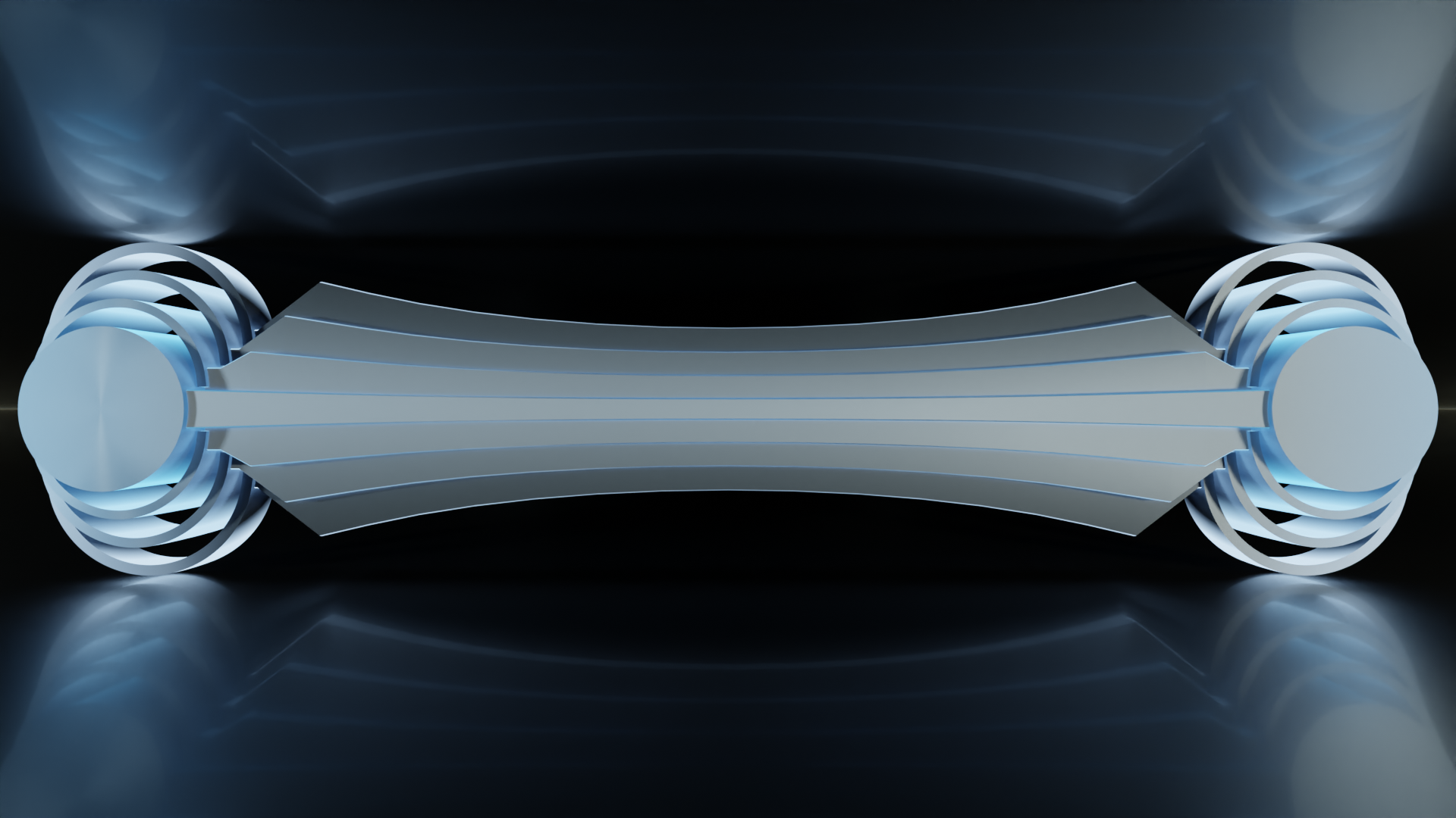
With this, we can visualize an end to end connection. On one end, starting with the core of application data, the packet is encapsulated with layers, sent down a line, received, decapsulated, and handed to the receiving application. What's more, if we shift perspectives a bit and lay this on its side, we can see that the layers still even resemble the classic representation of the stack.
So far, nothing in between the source and the destination is represented yet. But we can start imagining what might be required to fit in. And the taper in the middle, even though it's more of a stylistic feature, gives us another clue.
I'll refer back to the mesh topology exploration in the VLAN article (specifically, Getting Down to Brass Tacks). In that, we took a look at what topological effects would come from pinning a Post-It note to a cork board using a thumb tack. In doing so, the Post-It note and cork board were topologically transformed. Most notably, the note went from being basically scaled cube to having more in common topologically with a torus. It had its boundary manifold fundamentally altered by the process.
In this case, we can picture the data being transmitted as the pin (the topology that defines the rest), the devices on either end of the connection as cord boards (terminal end points that have topology that conforms to the defining topology), and network devices along the way as Post-It notes (acting as passthroughs).
So what about frames and packets, then? These simply refer to the hierarchy of data within layers as they traverse through a network. Communication between devices on a network happens in a stream of bits. Different devices examine different aspects of the data and make decisions about what to do with it.
Some devices only look at a portion called a frame. Frames coincide with the Link/Data Link layer, on the TCP/IP and OSI models respectively. The frame contains hardware address information about where it's coming from and where it's going to. The hardware address is also called a MAC (Media Access Control) address. These addresses are used by layer 2 (using OSI numbering) devices. Layer 2 switches are one example, but physical interfaces in general are layer 2 devices meaning they access the stack up to and including layer 2.
Other devices are capable of examining the packet level, which corresponds with the Network/Internet layer. This layer contains IP address information. While hardware addresses aren't intended to leave a local network, IP addresses are used for routing through the internet as a whole. The key takeaway from the delineation is that two sets of addressing schemes are used. One for local, and one for global. Layer 3 (OSI numbering) devices are capable of inspecting these addresses in order to route traffic to the correct destination.
Firewalls need access to the transport layer, also known as segments, so they can be considered layer 4 devices. And there are even some network appliances that examine the application layer, such as some intrusion detection systems and certain types of proxies. So all the way through the stack, we can potentially have equipment that can interface with all of it. (Note that this doesn't necessarily imply that your data is being read every step along the way. The application layer is commonly encrypted, or at least should be. But use of encryption doesn't imply that data is unreadable. That's a topic for another article though.)
Let's take a quick look at how this is usually represented, and see if we can get it to mesh well with our working model.
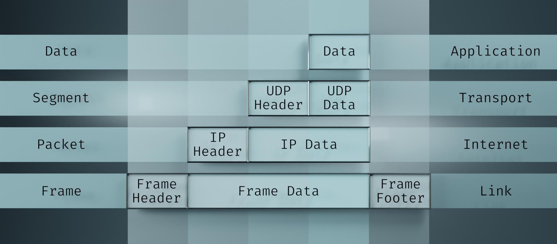
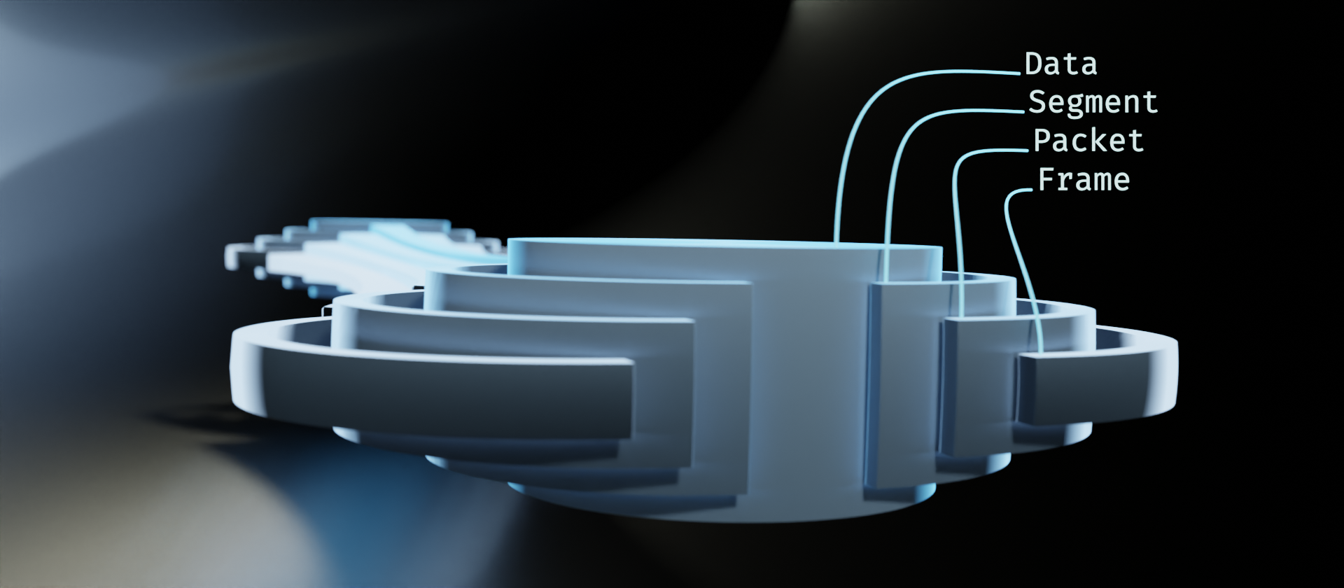
The feature I'd like to draw the most attention to is the usage of vertical columns. Starting at the top with the Data block, if we follow that down through the layers, we can see that it stays in place. It just becomes increasingly encapsulated as it goes. In the Segment layer, the UDP Header gets tacked on. In the Packet layer, it gets an IP Header. And in the Frame layer, it gets a Frame Header and Footer. But all through that process, the Data block persists in its place.
This view of the layers is actually what gave me the idea of Matryoshka dolls in the first place. It adds an extra dimension to the one-dimensional layer ordering by providing the columns to show the encapsulation. From this, I simply added another extra dimension to show transit of information. So this fits in nicely.
We do lose a little bit of information in the translation here. This is due to the principle mentioned in part 1, "Simplistic diagrams are limited to simplistic concepts." We lose details about the frame containing both a header and a footer, for example. There are other details about the original diagram that lend themselves better to visualizing the encapsulation in terms of the bitstream, as well. For the purpose of this visualization, however, those details are somewhat extraneous. We are aiming to visualize the stack as it moves through a network.
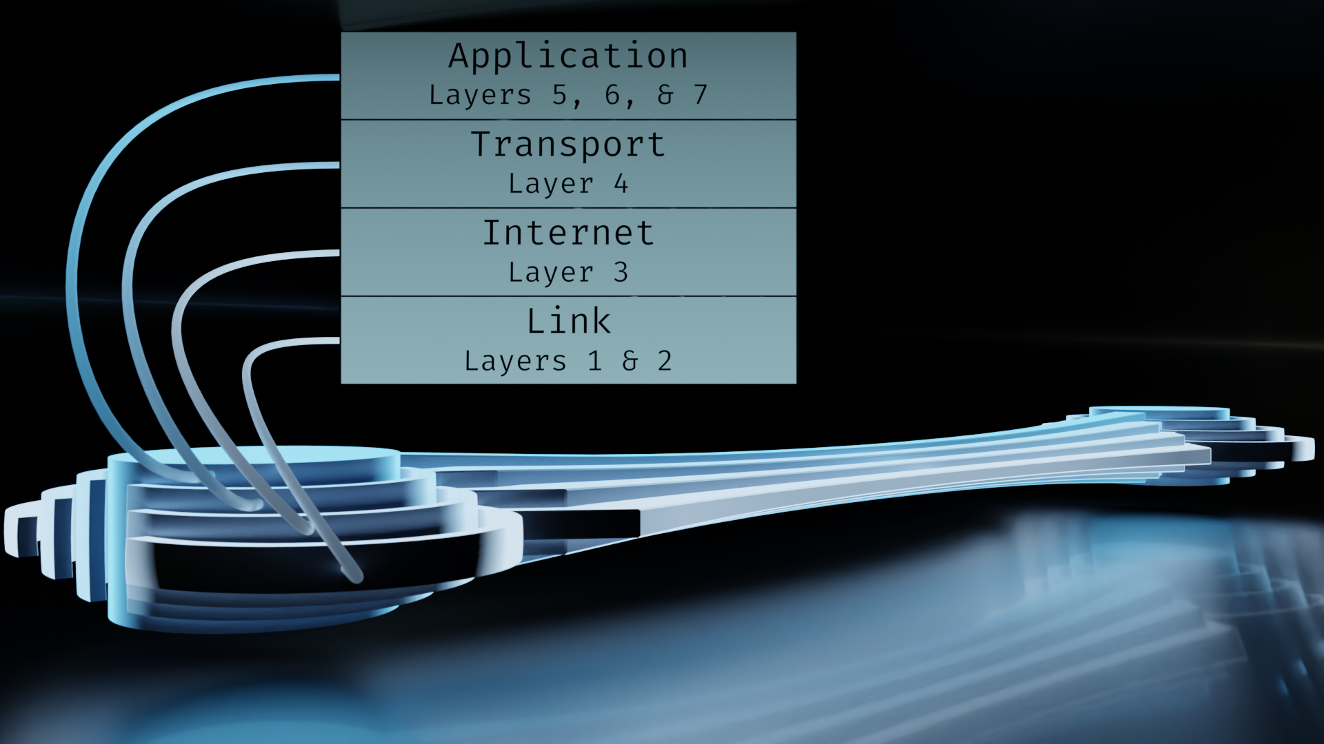
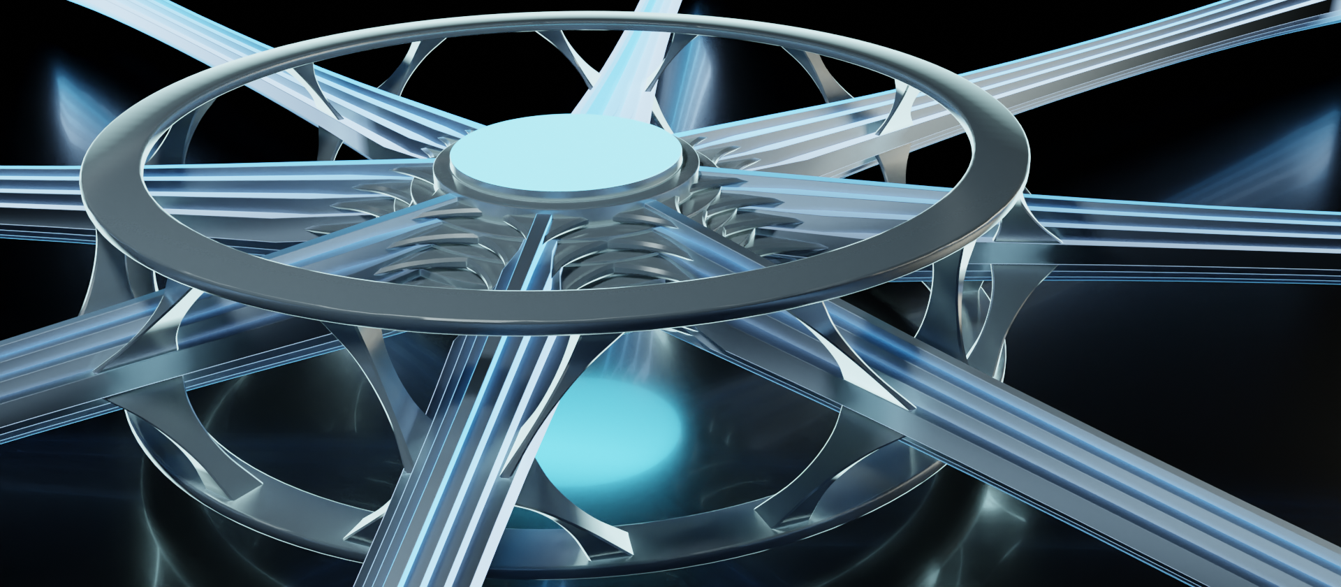
So let's take a look at how this might fit into a network device.
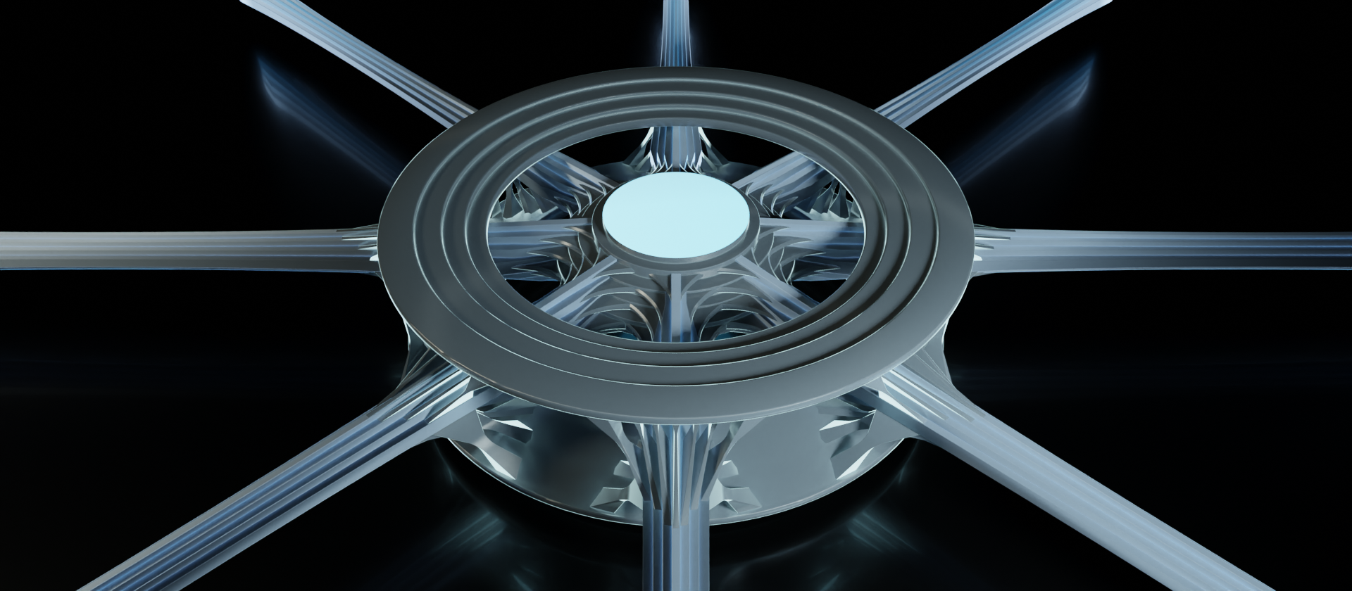
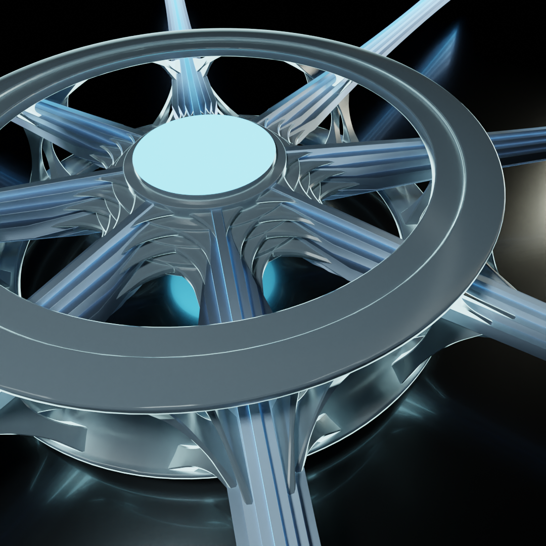
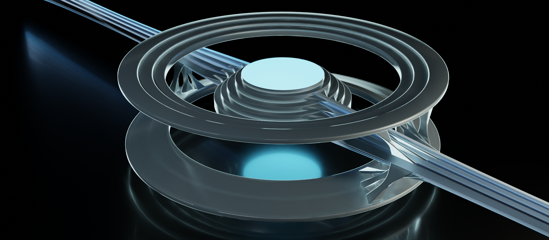
There's quite a bit to take in here. The main components to take note of are the data streams, outer ring, inner core, and linkages. These are just informal terms we'll temporarily use for the abstractions we're translating. Let's take another look from the top and break out the individual components.
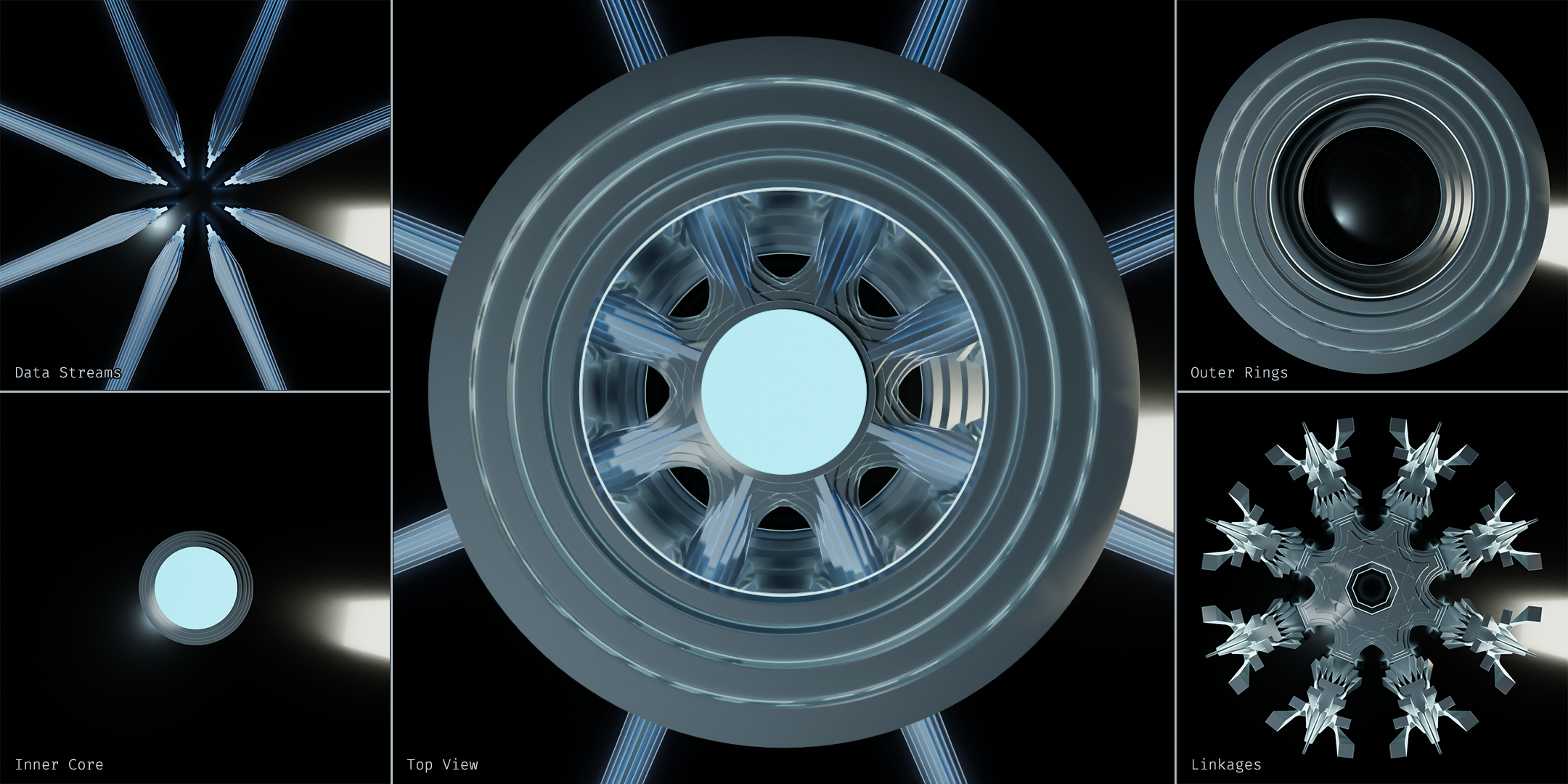
The data streams are easy enough. Those are all of the incoming/outgoing connections to other devices on this network. Even when we're looking at it from the top like this, we can still discern the stack of layers.
The inner core represents the connectivity between data streams. It's a way of showing that these data streams all have potential to be passed along. In other terms, this shows the connections are within the same broadcast domain.
The outer ring represents the device's interface to the data stream. All network devices perform some sort of programmatic operations on the given data stream to varying degrees, and this is where those operations are performed. For this example, our outer rings have four layers, implying they are accessing all layers of the stack. We'll look at other examples shortly.
The complicated looking tech-snowflake in the image above is comprised of the linkages. The linkages show how the data stream is interfaced by both the outer ring and the inner core. They're the topological features that connect everything together in an orderly fashion. And since the objective of this exercise is to visualize topology of the flow of data through the devices within a network, this strange little snowflake is the star of the show.
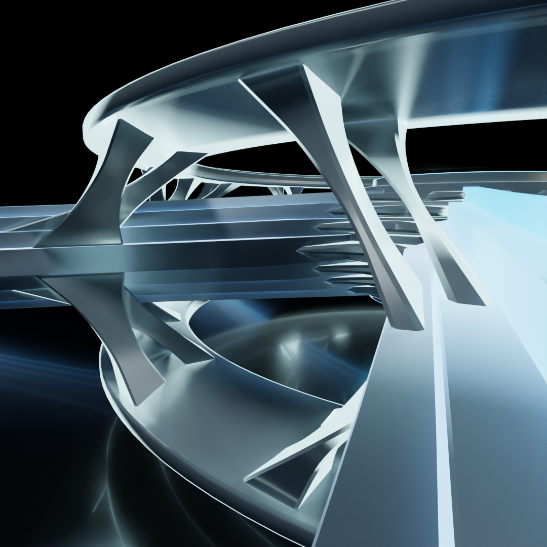
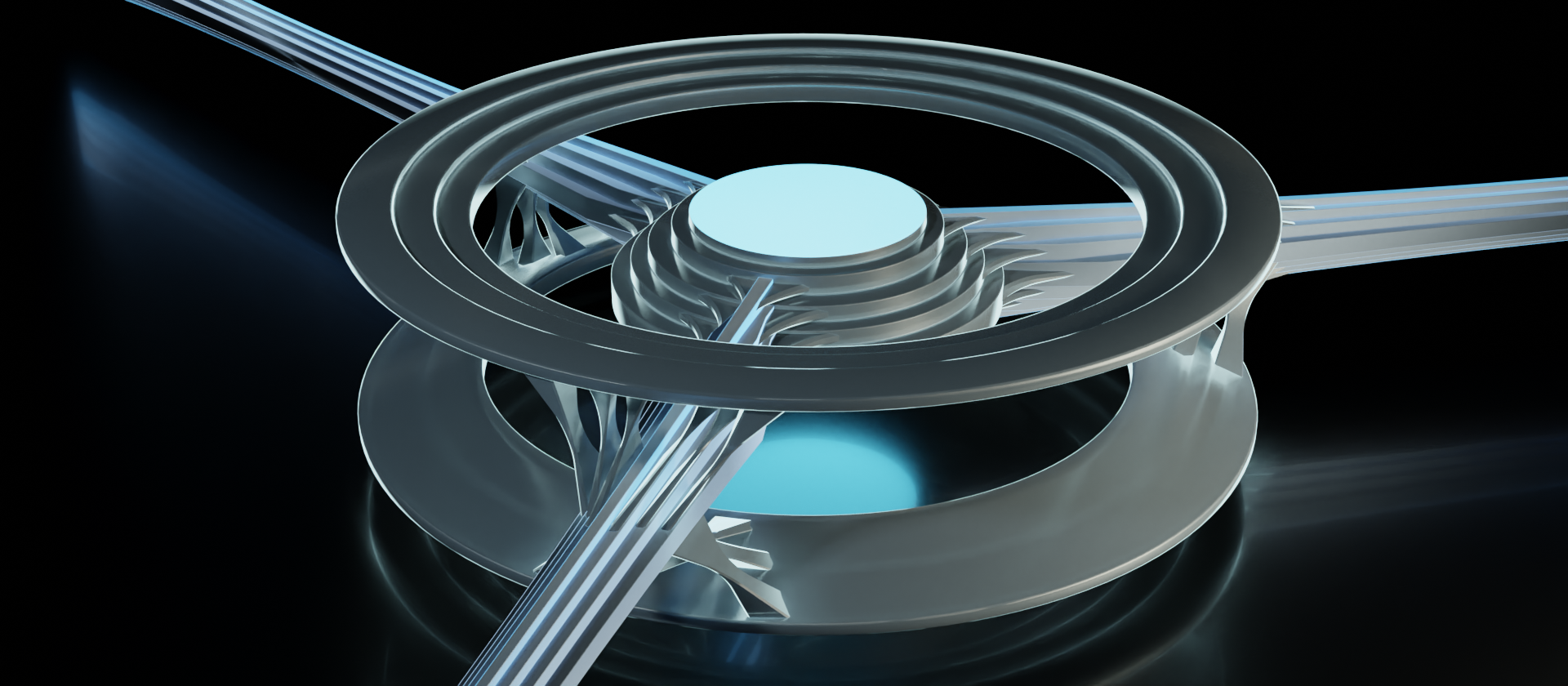
This "completely decked out" example of the device accessing all the layers isn't particularly common though, and feels a bit stifling. So let's take another look at it in a different context.
In this example, the outer rings only access the link layer (layers 1 and 2 of the OSI model). So this could easily represent a network switch that only needs the link layer to do its job. There is only a single set of linkages connecting the data stream to a single set of outer rings.
But when we look at the inner core, we can still see that the information that gets passed through to other connections still contains all layers of the stack. The inner core itself retains the features for all of the layers, and the linkages are still present. That's because the data stream going through this node is not diminished by it. While the device might be able to read and possibly alter aspects of the link layer, the stack as a whole still passes through.
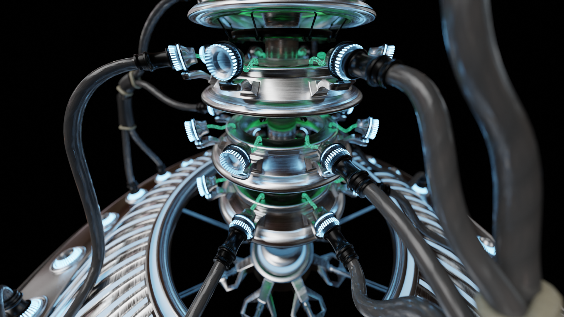
So let's take a look around what a layer 3 device would look like, and what it might be capable of doing.
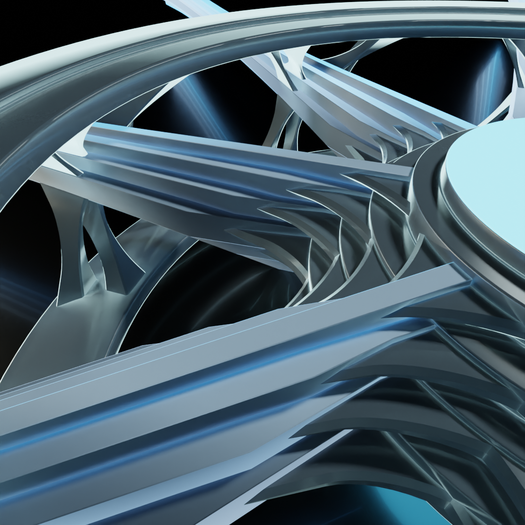
The outer rings now have an additional feature to illustrate the addition of a layer, as well as another set of linkages to the data stream to match. This layer 3 device (again, up to and including layer 3 of the OSI model, coinciding with the Internet layer of the TCP/IP model) would be capable of accessing both the MAC hardware addressing information from the Link layer as well as the IP addressing information from the Internet layer. Such a device is likely performing some sort of routing function.
This model would work well within a flat network, but what about cases of networks using subnets or VLANs? Could we add in more central cores to illustrate network segmentation? Perhaps we could expand the design vertically and make a stack of stacks.
This vertical stack is an intriguing idea. We'll get more into that later though. First, let's go into a little bit more detail about the relationship between the outer rings and the inner core, the processes that we can attribute to them, and the limitations of this model.
Broadcast domain interconnectivity is an essential component of network topology. That "inner core" of our imaginary network device is effectively acting as what's known as a bridge. Bridging is a mechanism for ganging network interfaces together into a pool.
This is where it gets tricky, using simplified models to represent what's going on though. Because we separated the concepts of device logic and interconnection, we also have the implication that the device doesn't perform logical operations on connection states, which is not at all the case.
Recalling back to a previous concept in the series, we went over the idea of a switch as a sprinkler head. I joked about hooking a hose up to a port and having water spray out of all of the other ports, and I mentioned the idea of "gates" controlling the flow into and out of the switch.
Hook up a hose, plug two of the holes, and the water will spray out of the remaining hole.
This is largely the logic being performed within the device. Whether and what to pass along, and where to pass it to. So while the block above can also be thought of as a bridge of sorts, it lacks any topological features to indicate the logic of functions.
Looking again at our imaginary network device monstrosity riddled with topological linkages, we can envision this process to a certain degree. Let's look at one last set of examples of it to simply things a bit more.
This device is hooked into the all the layers up to the transport layer, so it would be referred to as a layer 4 device (layers 1-4 of the OSI model). So this could be a firewall, for example. Firewalls need to examine the transport layer for port data, which enables them to selectively allow or deny traffic based off the set of rules they use.
I depicted only two data stream connections here to simplify matters a bit so that we can visualize the flow of data in strictly linear terms. So let's say that the data coming into the firewall is from an upstream connection in the upper left. It is inspected by the device, accessing up to the transport layer, and passes the rule set to subsequently be passed along (if it didn't pass, it would be dropped right there and then). From the inner core, there is only one other connection it can go. On its way back out of the device to the lower right, it is then inspected again to ensure that it passes the set of rules.
Now we've got the same deal, but with two downstream connections. After the data is passed through to the inner core, it then goes out to both connections. Let's say the connection to the right is the correct destination, while the connection lower down is incorrect. The destination will be examined on the way out of the device. For the connection to the right, the destination will be verified to be correct and passed along to proceed to its destination. If it's incorrect, as in the case of that lower connection, it will get dropped, never be received by the far end of the connection.
This explanation allows for the separation of those concepts of device logic and interconnection. It's important to note, though, that thinking of the device logic and the bridge as being separate does not always play nicely.
Mikrotik's Packet Flow chart is a great example of how these simplifications can be rendered insufficient in short order. But as a general mental model, this kind of visualization has helped me significantly to grapple with more complex details as I come across them. While simplified models are rarely ever perfect, they can be useful tools for understanding specific elements of a complex system.
In the next and final part, we'll head back to take another look at the SSFBSGLSWT (strange sci-fi Battlestar Galactica lookin' sub-woofer thing) and why I made such an odd thing to begin with. Hopefully, you've already got some guesses as to the meaning behind of some of its odd features.
Link will be available here once it's published. Until then, and as always, if you have any suggestions or corrections for me to take into account, please let me know! I tried to make this as orderly as I could, but whether you're an experienced technical engineer, just starting out, or simply reading through out of curiosity, if you feel that there are any sections that need improvement I'd appreciate the feedback.